
průtokoměry GM 50 A
Pro více informací, prosím, kontaktujte prodejce:
- Ing. Vojtěch Kroupa
- +420 736 473 797
- vojtech.kroupa@labtech.eu
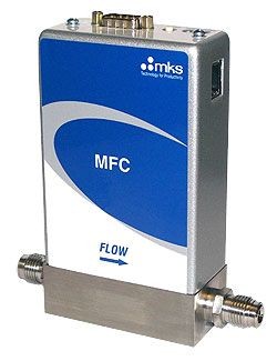
Technická specifikace
| Full Scale Flow Ranges | 5 - 50000 sccm (N2 equivalent) (consult factory for available flow ranges) |
| Maximum Inlet Pressure | 150 psig (can not exceed pressure differential requirement across MFC) |
| Normal Operating Pressure Differential | 5 to 5000 sccm; 10 to 40 psid 10000 to 20000 sccm; 15 to 40 psid 30000 to 50000 sccm; 25 to 40 psid (N2 Full Scale) (with atmospheric pressure at the MFC outlet) |
| Proof Pressure | 1000 psig |
| Burst Pressure | 1500 psig |
| Control Range | 2% to 100% of Full Scale (range on mech.) |
| Typical Accuracy | ±1% of setpoint for 20 to 100% Full Scale ± 0.2% of Full Scale for 2 to 20% Full Scale (with N2 calibration gas) |
| Repeatability | ± 0.3% of Reading |
| Resolution | 0.1% of Full Scale |
| Temperature Coefficients | |
| Zero | <0.05% of Full Scale/°C |
| Span | <0.08% of Reading/°C |
| Inlet Pressure Coefficient | <0.02% of Reading/psi |
| Typical Controller Settling Time | <750 msec, typical above 5% (per SEMI Guideline E-17-0600) |
| Warm-up Time | <30 minutes (to within 0.2% of Full Scale of steady state performance) |
| Operating Temperature Range | 10°C to 50°C (Ambient) |
| Storage Humidity | 0 to 95% Relative Humidity, non-condensing |
| Storage Temperature | -20° to 80°C (-4° to 149° F) |
| Fittings | Compatible with Swagelok® 4 VCR® male, 1/4 inch Swagelok® compression seal, surface mount, Swagelok® 8 VCR® male, 1/8 inch Swagelok®, 1/2 inch Swagelok®, 6 mm Swagelok®, 8 mm Swagelok® |
| Leak Integrity | |
| External | <1 x 10⁻¹⁰ (scc/sec He) |
| Through closed valve | <1.0% of Full Scale at 40 psig inlet to atmosphere (To assure no flow-through, a separate positive shut-off valve is required.) |
| Wetted Materials | |
| Standard | 316L S.S. VAR (equivalent to 316 S.S. SCQ for semiconductor quality), 316 S.S., Elgiloy®, Nickel |
| Valve Seat | Teflon® (MFC only) |
| Surface Finish | |
| MFC | 10µ inch average Ra |
| MFM | 16µ inch average Ra |
| Weight | less than 3 lbs (1.4kg) |
| Compliance | Compliant to EMC Directive 2004/108/EC |
| Electrical Analog I/O Input Power Required | +15 to +24 VDC @ (<4 watts) |
| Electrical Analog I/O Flow Input/Output Signal | |
| Voltage | (0 to 5 VDC) 15 pin Type "D" male, 9 pin Type "D" male |
| Current | (4 to 20 mA) 15 pin Type "D" male |
| Input Power Required | |
| DeviceNet™ | +11 to +25 VDC per (<4 watts) |
| RS-485 | +15 to +24 VDC per (<4 watts) |
| Profibus® | +15 to +24 VDC per (<4 watts) |
| EtherCAT® | +24 VDC per (<5 watts) |
| Connector | |
| DeviceNet™ | 5 pin micro connnector (power and comm.) |
| RS-485 | 9 pin Type D male (power and comm.) |
| Profibus® | 9 pin Type D male (power); 9 pin Type D female (comm.) |
| EtherCAT® | 2 x RJ-45 (comm.) male; M8 male, 5 pin (power) |
| Data Rate Switch/Selection | |
| DeviceNet™ | 4 positions: 125, 250, 500K (Default)programmable over network |
| RS-485 | No switch Set Data Rate via RS485 |
| Profibus® | Set Data Rate via Profibus |
| EtherCAT® | No switch |
| Comm. Rate(s) | |
| DeviceNet™ | 125 Kbps, 250 Kbps, 500 Kbps |
| RS-485 | 9.6 Kbps, 19.2 Kbps, 38.4 Kbps |
| Profibus® | 9.6 Kbps to 12 Mbps |
| EtherCAT® | 100 Mbps |
| MAC ID Switches/Addresses | |
| DeviceNet™ | 2 switches, 10 positions; 0,0 to 6,3 ; 1 to 254 |
| RS-485 | Set address over RS485; Station Addresses 0,0 to 9,9 |
| Profibus® | 2 switches, 10 positions |
| EtherCAT® | 3 switches, 16 positions |
| Network Size | |
| DeviceNet™ | Up to 64 nodes |
| RS-485 | Up to 32 nodes |
| Profibus® | Up to 99 nodes |
| EtherCAT® | Up to 4095 nodes |
| Visual Communication Indicators | |
| DeviceNet™ | LED network status (green/red) LED module status (green/red) |
| RS-485 | LED Comm (yellow) LED Error (red) |
| Profibus® | LED Comm (green/red) LED Error (green/red) |
| EtherCAT® | LED Power (green) LED Run (green) LED Error (red) LED /Comm (green) |
Máte dotaz?
Pole označená (*) musí být vyplněna
LABTECH s.r.o © 2011, Polní 23/340, CZ 639 00 Brno, Tel: +420 511 110 711, Fax: +420 543 210 115, info@labtech.eu