
průtokoměr P9B
Pro více informací, prosím, kontaktujte prodejce:
- Ing. Vojtěch Kroupa
- +420 736 473 797
- vojtech.kroupa@labtech.eu
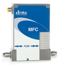
Technická specifikace
| Full Scale Flow Ranges | 5 - 50000 sccm (N2 equivalent) consult factory for available flow ranges |
| Maximum Inlet Pressure | 150 psig (cannot exceed pressure differential requirement across MFC) |
| Normal Operating Pressure Differential | 10 to 5000 sccm; 10 to 40 psid 10000 to 20000 sccm; 15 to 40 psid 30000 to 50000 sccm; 25 to 40 psid (N2 Full Scale) (with atmospheric pressure at the MFC outlet) |
| Proof Pressure | 1000 psig |
| Burst Pressure | 1500 psig |
| Control Range | 2% to 100% of Full Scale (range on mech.) |
| Typical Accuracy | ± 1% of setpoint for 20 to 100% Full Scale ± 0.2% of Full Scale for 2 to 20% Full Scale |
| Repeatability | ± 0.3% of Reading |
| Resolution | 0.1% of Full Scale |
| Temperature Coefficients | |
| Zero | < 0.05% of Full Scale/°C |
| Span | < 0.08% of Reading/°C |
| Inlet Pressure Coefficient | < 0.02% of Reading/psi |
| Typical Controller Settling Time | < 750 msec., typical above 5% Full Scale (per SEMI Guideline E-17-0600) |
| Warm-up Time | < 30 minutes (to within 0.2% of Full Scale of steady state performance) |
| Operating Temperature Range | 10°C to 50°C (Ambient) |
| Storage Humidity | 0 to 95% Relative Humidity, non-condensing |
| Storage Temperature | -20° to 80°C (-4° to 149° F) |
| Pressure Display | 0 to 100 psia |
| Pressure Readout Units | psia, kPA |
| Pressure Accuracy | 1% Full Scale |
| Pressure Resolution | 0.1 psia |
| Temperature Display | 0 to 100°C |
| Temperature Readout Units | °C |
| Temperature Accuracy | ± 2°C |
| Temperature Resolution | 0.1°C |
| Attitude Insensitivity | 0.25% of Full Scale for indicated zero, span and actual span |
| Pressure Transient | ±5% of setpoint from 20 to 100% of Full Scale when subject to a 2 psi inlet pressure transient (Inlet/Outlet Pressure Sensitivity) |
| Fittings | Compatible with Swagelok® 4 VCR®, 11/8 inch surface mount (C-seal, W-seal), 11/2 inch W-seal |
| Display | 4 digits for value 4 characters for unit |
| Leak Integrity | |
| External | < 1 x 10⁻¹⁰ (scc/sec He) |
| Through closed valve | < 1.0% of Full Scale at 25 psig inlet to atmosphere (range on mech.) To assure no flow-through, a separate positive shut-off valve is required. |
| Wetted Materials | |
| Standard | 316L S.S. VAR (equivalent to 316 S.S. SCQ for semiconductor quality), 316 S.S., Elgiloy, KM-45 |
| Valve Seat | PTFE (Teflon) |
| Surface Finish | 10µ inch average Ra |
| Weight | less than 3 pounds (1.4kg) |
| Compliance | CE Compliant to EMC Directive 2004/108/EC |
| Input Power Required | |
| DeviceNet™ | +11 to +25 VDC per DeviceNet specification (@ <3.5 watts) |
| RS-485 | +15 to +24 VDC @ 350mA max |
| Connector | |
| DeviceNet™ | 5 pin microconnnector (DeviceNet) |
| RS-485 | 9 pin Type D male |
| Data Rate Switch | |
| DeviceNet™ | 4 positions: 125, 250, 500K (Default), PGM (programmable over the network) |
| RS-485 | 3 positions: 9.6, 19.2, 38.4K (Default) |
| Data Rate/Network Length | |
| DeviceNet™ | Data Rate (User Selectable) 125 Kbps, 500 meters (1,640 feet) 250 Kbps, 250 meters (820 feet) 500 Kbps, 100 meters (328 feet) |
| RS-485 | Data Rate (User Selectable) 9.6 Kbps, 1200 meters (4,000 feet) 19.2 Kbps, 1200 meters (4,000 feet) 38.4 Kbps, 1200 meters (4,000 feet) |
| MAC ID Switches | |
| DeviceNet™ | 2 switches, 10 positions 0,0 to 6,3 are hardware ID numbers 7,0 to 9,9 are software ID numbers 6,4 to 6,9 are unused and, if selected will default to hardware ID number 6,3 |
| RS-485 | 2 switches, 10 positions; 0,0 to 9,9. Available MAC IDs are 3,2 to 9,9. |
| Network Size | |
| DeviceNet™ | Up to 64 nodes |
| RS-485 | Up to 32 nodes |
| Network Topology | |
| DeviceNet™ | Linear (trunkline/dropline) power and signal on same network cable |
| RS-485 | Master/slave |
| Visual Communication Indicators | |
| DeviceNet™ | LED network status (green/red) LED module status (green/red) Scrolling LED displays (MFC Type, Flow Full Scale, Gas Type, IP address, Instance Number (1 to 31)) |
| RS-485 | LED network status (green/red) LED module status (green/red) Scrolling LED displays (MFC Type, Flow Full Scale, Gas Type, IP address, Instance Number (1 to 31)) |
Máte dotaz?
Pole označená (*) musí být vyplněna
LABTECH s.r.o © 2011, Polní 23/340, CZ 639 00 Brno, Tel: +420 511 110 711, Fax: +420 543 210 115, info@labtech.eu